How Transformers Work
 There
are many sizes, shapes and configurations of transformers from tiny to gigantic like those
used in power transmission. Some come with stubbed out wires, others with screw or
spade terminals, some made for mounting in PC boards, others for being screwed or bolted
down.
There
are many sizes, shapes and configurations of transformers from tiny to gigantic like those
used in power transmission. Some come with stubbed out wires, others with screw or
spade terminals, some made for mounting in PC boards, others for being screwed or bolted
down.
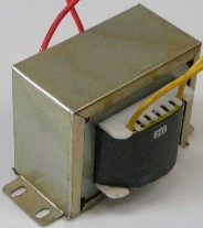
Transformers are composed of a laminated iron core
with one or more windings of wire. They are called transformers because they transform
voltage and current from one level to another. An alternating current flowing through
one coil of wire, the primary, induces a voltage in one or more other coils of wire, the
secondary coils. It is the changing voltage of AC current that induces voltage in the
other coils through the changing magnetic field. DC voltage such as from a battery or DC
power supply will not work in a transformer. Only AC makes a transformer work.
The magnetic field flows through the iron core. The faster the voltage changes, the
higher the frequency.
The lower the frequency, the more iron is required in
the core for the efficient transfer of power. In the USA, the line frequency is 60
Hertz with a nominal voltage of 110 volts. Other countries use 50 Hertz, 220 volts.
Transformers made for 50 Hertz must be a little heavier than ones made for 60 Hertz because
they must have more iron in the core. Line voltage can vary a little and usually runs
between 110 volts and 120 volts or between 220 and 240 volts depending on country or power
connections. A house in the USA has 220 volts coming in but is split to two legs of
110V by grounding the center tap (see configuration section below)
The ratio of input voltage to output voltage is equal
to the ratio of turns of wire around the core on the input side to the output side. A
coil of wire on the input side is called the primary and on the output side is called the
secondary. There can be multiple primary and secondary coils. The current ratio
is opposite the voltage ratio. When the output voltage is lower than the input
voltage, the output current will be higher than the input current. If there are 10
times the number of turns of wire on the primary than the secondary and you put 120 volts on
the primary, you will get 12 volts out on the secondary. If you pull 2 amps out from
the secondary, you will only be using 0.2 amps or 200 milliamps going into the primary.
Transformers can be built so they have the same number
of windings on primary and secondary or different numbers of windings on each. If they
are the same, the input and output voltage are the same and the transformer is just used for
isolation so there is no direct electrical connection (they are only linked through the
common magnetic field). If there are more windings on the primary side than the
secondary side, then it is a step down transformer. If there are more windings on the
seconday side, then it is a step up transformer.
A transformer can actually be used in reverse and will
work fine. For example, if you have a step up transformer built for transforming 120
volts to 240 volts, you can also use it for a step down transformer by putting 240 volts
into the secondary side and you will get 120 volts on the primary side. Effectively,
the secondary becomes the primary and vice versa.
Transformer Power Ratings
Voltage is measured in volts, current is measured in
amps, and the unit of measure for power is watts. Watts is equal to the volts times
the amps. There is a little loss of power in a transformer due to the combination of
resistance and reactance. Reactance is similar to resistance except it is the
resistance to an AC current or more technically, the resistance to change in a change in
current due to the change in the field created. This heat is what limits the amount of
current or power a transformer can handle. The higher the current, the more heat is
produced. When the wires get too hot, the insulation breaks down and shorts with
adjacent wires which causes more heat which eventually melts wires and ruins the
transformer.
A basic transformer has no additional components and so
nothing to protect it from overloading. If you were to connect the two output wires
directly together, that will constitute a short circuit and cause far too much current to
flow in both the primary and secondary and you will burn out the transformer. In the
same way, if you use the transformer to power a hot wire foam cutter and you are using a
wire with too little resistance for your foam cutter, you will burn out your transformer if
you don't have it protected by a proper value fuse or breaker. You have to make sure
that the wire resistance, in other words, the gage or diameter, and the length is correct to
limit the amount of current to under the rating of the transformer.
The higher the current, the larger the wires need to be
that carry that current. When the wires are larger, there is less resistance and so
less heat. The power that is changed to heat and lost can be calculated as P=I2R.
That means that if you double the current, the power lost to heat increases by four times.
If the transformer is a step down transformer, then there will be more current on the output
and so the wire in the secondary windings will be heavier than the primary. The
reverse is true for a step up transformer.
A transformer may be rated in Amps, Volt-Amps (VA), or
Watts (W). For small transformers, VA and Watts are the same thing for all practical
purposes. In large industrial transformers, power factors get involved and the two can
be different. If the transformer is rated in amps, it usually says X amps at X volts
and is rated on the output or secondary side. A 120V transformer with 24V out rated at
2 amps means that you can only safely pull 2 amps from the secondary side. You can
find the power rating of the transformer by multiplying the rated amps times the output
voltage so 2 X 24 = 48 watts.
If the transformer is rated in VA or watts, you can
calculate the maximum allowable output current by dividing the VA or watts by the output
voltage. So if the transformer is rated at 48 VA with 24 volts output, the allowable
output current is 48 / 24 = 2 amps.
Transformer Configurations
 A
120 volt transformer with two wires in and two wires out is very simple. You hook up
the two wires on the primary side, the 120V side, to a wall outlet and your output voltage
is on the two wires coming from the secondary side.
A
120 volt transformer with two wires in and two wires out is very simple. You hook up
the two wires on the primary side, the 120V side, to a wall outlet and your output voltage
is on the two wires coming from the secondary side.
When a transformer is shown in an electronic circuit,
it is shown as a diagram like shown here. The parallel lines represent the laminated
iron core, the curved lines represent the primary and secondary windings, the circles
represent the terminations whether terminals or short wires.
Center Tap
A common configuration is a center tap or CT. The
secondary side has three wires out. The middle wire on the output side is attached to
the secondary coil, usually at the middle. If the winding ratio is 5 to 1, then with
120V input, you get 24 volts output on the two outside wires but if you connect an
outside wire and the center wire, you get 12 volts because you are using only half the
secondary winding making the connection a 10 to 1 ratio. If the transformer is rated
at 2 amps, you still can only use 2 amps output whether you use 12 volts or 24 volts.
Often the center tap is grounded so you then have two 12 volt sources that can be used to
make + and - 12V DC after running through a converter (rectifier and filter).
Dual Output
 The
dual output configuration is similar to the center tap except that instead of connecting a
wire to the center of the coil, the coil is separated into two separate coils with wires
with terminals or wires coming out from both ends of both coils so four wires come out of
the secondary side instead of three.
The
dual output configuration is similar to the center tap except that instead of connecting a
wire to the center of the coil, the coil is separated into two separate coils with wires
with terminals or wires coming out from both ends of both coils so four wires come out of
the secondary side instead of three.
If the transformer is a 110V input with two 12V
outputs, you can connect the two secondary coils in series to get 24 volts out, or you can
connect them in parallel to get 12V out. You have to be careful to connect the right
ends of the two secondary coils in both the series and in the parallel connections. If
you reverse the connections, you will get 0 volts out because the two voltages will cancel
each other out.
If the transformer is rated at 48VA, then you can use
up to 2 amps out for the 24 volt connection which is no different than the center tap or
single 24V output configuration. However, when connected in parallel, you get 12 volts
out but double the output current available so you can get 4 amps out. You get the
full 48VA output where with the center tap 12V output, you can only get half the rated
output or 24VA. This is an advantage in hot wire foam cutters because you have a wider
range of wire diameters and lengths depending on whether you connect the outputs in parallel
or series. The series and parallel connections are shown below.
Dual Input
 The
dual input transformer is often used to make the transformer able to be used in both
countries with 120V line voltage and 240V line voltage. The primary is separated into
two separate windings with terminals at each end of both windings so there are four wires or
terminals on the primary side.
The
dual input transformer is often used to make the transformer able to be used in both
countries with 120V line voltage and 240V line voltage. The primary is separated into
two separate windings with terminals at each end of both windings so there are four wires or
terminals on the primary side.
To use it with 110 volts input, the two primary
windings are connected in parallel as in the left diagram below. Care must be taken to
connect the correct ends together. If they are reversed, the fields cancel each other
out because the fields generated by each section of the primary are opposite.
Normally, terminals are labeled with numbers or letters and a diagram is provided on the
transformer or in an accompanying data sheet showing how the connections must be made for
110V and 220V.
If the transformer is to be connected to a 220V supply,
then the two coils are connected in series and again, care must be taken to connect the
correct terminations together. Parallel connections for 110V and series connections
for 220V is shown below.
Dual Input and Output
And of course, you can have both a dual input and a
dual output so you have four wires in and four wires out which gives even more flexibility
to the use of the transformer.
Some specialized transformers may have several
secondary taps or several secondary windings to provide different voltages and they need not
be even numbers. A transformer could have a 3V, 5V, 12V, and 24 volt output for
example.
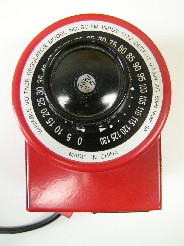
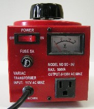
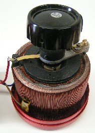
Autotransformers (Variac)
An autotransformer is often referred to as a Variac
which is actually one company's trade name for their autotransformer. It has a
continuous output voltage from zero to a little over the input value. It works similar
to a potentiometer or rheostat except the change in the voltage is due to the field change
rather than resistance. Another difference is that a potentiometer or rheostat is very
inefficient because it converts the current flowing through it to heat (Watts = Amps X
Volts). As in all transformers, the resistance is low so the amount of heat generated
is much less and so much more efficient at transforming voltage
An autotransformer has only one winding which serves
as both the primary and the secondary winding. Because there is only one winding,
there is no electrical isolation between the input and the output but if isolation is not
required, then it provides an alternative to multiple winding transformers in some
situations.
This transformer has the input wires connected to one
end of the winding and the other a little ways from the other end. The secondary is
connected the same point as the input side that is on the end. The other secondary
connection is to a wiper that rides on the top of the windings where the insulation has been
removed so the wiper can make contact with the windings at any point on one surface.
The wiper is connected to a knob on the top of the autotransformer so a person can turn the
knob to get the voltage they want. Because one primary wire is connected a ways from
the end of the winding, the wiper can go past that point and so provide a voltage higher
than the input, typically a 110V output can go up to around 130V on the secondary side.
 |
 |
Because the autotransformer has only one winding,
there is only one wire size and so the maximum input current is also the maximum output
current. If a 110 Volt autotransformer is rated at 10 amps, then the maximum output
current is 10 amps regardless of the voltage. If it is rated in Watts or VA, then the
amps is calculated by dividing the Watts or VA by the rated input voltage.
The autotransformer is a good alternative to a step
down transformer when the range of desired voltages is on the high end or the whole range of
voltages is needed but becomes more expensive if the range is on the low end because you
have a lot of unused windings. A step down transformer is more economical.
For hot wire foam cutting, an autotransformer is much
more expensive than step down transformers in most applications. If the voltage
required is more than 24 volts, then an autotransformer might be considered.
Phases and connecting multiple windings
For simplicity's sake, I have not mentioned phase but
when connecting two or more windings together, the phase becomes very important. AC
current is a sine wave and the voltage changes from positive to negative and back in a
sinusoidal rhythm many times per second. How often the voltage changes is called
frequency and used to be called cycles per second but is now called Hertz (abbreviated Hz).
Household current in the USA and some other countries is 60 Hz, in other countries is 50 Hz.
When talking about two wave forms such as you have in two windings, the relationship between
the two sine waves is the phase. If the sine waves line up, they are in phase, if the
positive peak of one wave lines up with the negative peak of the other wave, the two waves
are 180° out of phase. The phase between one end of a coil and the other are also 180°
out of phase. When one end is at the positive peak, the other end will be on the
opposite peak. Since there must be a difference in voltage between two points for
current to flow, the two ends of the winding must be opposite voltage at any point in time.
The phase difference between two windings depends on
the direction of windings and how they are connected so in electrical schematics a dot at
one end of the winding indicates the beginning of that winding. For simplicity's sake,
I have left the dots off the schematics in this article. However, when connecting two
coils together, it is very important to connect them correctly.
For a series connection you must connect the end of
one winding to the start of the other winding (windings for multiple coils are always wound
in the same direction). If you connect the start of one winding to the end of the
other winding in a series connection, the fields will cancel out and you will get zero
output. This will not hurt the transformer but you will get no output voltage.
When
connecting two windings in parallel, you must connect the start of one winding to the start
of the other winding and the two ends of the windings together. In a parallel
connection, connecting the wires in reverse will burn up your transformer if not
properly protected (proper current rating) by a fuse or circuit breaker. Be very
careful when connecting two coils together.
Further reading
This has basically just been an overview for a
layperson. Although physically a transformer is a fairly simple device with few parts,
how it actually works is pretty complicated. I recommend Rod Elliot's excellent
articles if you are interested in understanding them better:
Transformers - The Basics (Section 1),
(Section 2),
(Section 3)
He also has many other articles on electronics
including power supplies.